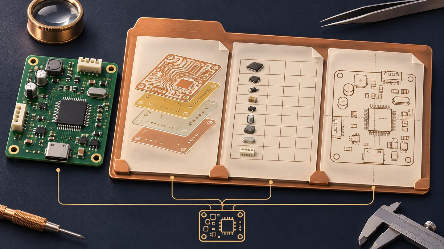
A PCB assembly package must describe three things consistently: the bare board to manufacture, the components to fit and the finished assembly to accept. Gerber files alone do not identify every purchased part or define how the product should be tested. A BOM alone does not establish physical placement. Treat the package as one controlled release, rather than a collection of recent exports.
Use this checklist before requesting a quote and again before authorizing production. It covers the handoff between files; the PCB BOM guide handles detailed parts-list fields and approved alternates. Agree the supplier’s accepted formats and the work included in the order before making the archive.
Separate Fabrication, Assembly and Acceptance Data#
A bare-board order needs the manufacturing definition. An assembly order adds population and placement information. Programming, functional testing, coating and mechanical work need their own instructions when included. Do not assume that uploading a schematic or a 3D rendering automatically requests those operations. Identify required deliverables, quantities and exclusions in a release note.
A File Handoff and Responsibility Matrix#
The following division is a proposed review workflow, not a statement that every supplier includes every check. Assign named owners for your order. The assembler can flag ambiguity, but changes to the product definition still need the customer’s authorized approval.
↔ Swipe horizontally to compare all columns
| Data package | Customer prepares | Supplier confirms |
|---|---|---|
| Fabrication | Layers, drills, stackup, drawing | File interpretation and process questions |
| Population | BOM, variant, DNP, supply split | Part availability and exceptions |
| Placement | Coordinates, side, rotation, drawing | Import conventions and orientation queries |
| Test and firmware | Procedure, limits, approved binary | Access, equipment and execution scope |
| Release control | Manifest, revision, approval owner | Exact package accepted for the build |
Check Gerber, Drill and Fabrication Requirements#
Include the intended copper layers, solder-mask layers, legends where required and a clearly identified board outline. Supply drill and routed-slot data with plated and non-plated features distinguishable. State stackup, finished thickness, copper requirements, material and surface finish in the fabrication specification. Any controlled impedance or special tolerance needs an explicit requirement and supplier agreement, not a guess from the board image.
Open the exported package in an independent viewer, such as the online Gerber viewer, and check alignment, scale, missing layers and the outline. This is a visual sanity check, not proof that all manufacturing limits are satisfied. If using an integrated format such as ODB++ or IPC-2581, confirm what it contains and what the receiving workflow still requires separately.
Match the BOM, Placement File and Assembly Drawing#
Export the BOM and placement data from the same released design and variant. Reconcile fitted reference designators across both files; explain DNP entries and parts intentionally excluded from automatic placement. The placement file should identify reference, X and Y, board side and rotation, with units and origin conventions documented. Confirm how bottom-side coordinates and angles are interpreted instead of applying an arbitrary mirror or rotation correction.
Provide readable top and bottom assembly drawings showing designators, pin 1, diode and capacitor polarity, connectors and any mechanical constraints. A placement file can be syntactically valid while a connector is reversed. For example, if the BOM removes R12 but the placement list still includes it, resolve the variant mismatch and regenerate the affected exports; do not ask the operator to choose between conflicting files.
Define Test, Programming and Supplied-Part Instructions#
When programming is ordered, identify the approved binary, version or checksum, target device, programming interface, configuration settings and verification method. Handle keys or device credentials through an agreed secure channel rather than a general quotation ZIP. For functional tests, specify power conditions, connections, sequence, pass/fail limits and the result record to retain. A schematic supports diagnosis but is not an executable test procedure.
For customer-supplied components, attach a packing list tied to BOM lines, quantities, packaging and handling notes. Agree shortages, attrition allowance and return of unused parts before shipment. State who provides test fixtures and programming adapters, who owns them and whether their preparation is part of the quote. The PCB testing guide explains why visual inspection, electrical checks and functional testing cover different risks.
Example ZIP Structure and Release Note#
Example only: use one top-level archive named Controller_RevC_Assembly_A.zip. Within it, 00_release contains the manifest and approval note; 01_fabrication contains Gerber, drill and fabrication specifications; 02_assembly contains BOM, placement and assembly drawings; 03_test contains agreed test and programming instructions. The manifest identifies the board revision, assembly variant, file versions, quantity basis and responsible contact. These names are an organizational suggestion, not a mandatory upload format.
Do not leave an old release beside the current files with names such as final-new or use-this-one. If a change is needed after submission, issue a replacement package with a change note and obtain acknowledgment of which release will be built. Ask the supplier to hold affected work until the discrepancy is resolved; an email attachment does not prove that an earlier production job was stopped.
Final Cross-File Checks Before Submission#
- Confirm that the manifest, drawings, BOM and placement data identify one board revision and assembly variant.
- Check that BOM quantities reconcile with unique fitted designators; document DNP and manual-assembly exceptions.
- Review top/bottom views, pin 1 and polarized parts against the released footprint and drawing, including components near board edges.
- Confirm board versus panel coordinates and quantities, supplier-owned panelization work and any required approval drawing.
- Verify that test limits, firmware identity and supply responsibilities are explicit; record unresolved questions instead of silently assuming answers.
Once the package is coherent, send it for PCB assembly review with the requested build quantity and delivery scope. Engineering questions should be closed through an agreed approval record. File completeness makes the review clearer; it does not by itself confirm material availability, manufacturing capability or a delivery date.
PCB Assembly File FAQs#
Are Gerber files enough to order PCB assembly?
No. Gerber-based fabrication data describes board features, while assembly also needs a parts definition and placement information. Include the BOM, placement file and assembly drawings, then add instructions for any ordered test, programming or special operation.
Can a PDF assembly drawing replace the placement file?
A drawing is valuable for human review, polarity and mechanical notes, but it does not reliably replace machine-readable coordinates. Agree any manual data preparation explicitly. Supplying both helps expose differences between the intended orientation and the exported data.
Should every file use exactly the same revision label?
Not necessarily: board, assembly and firmware can have separate revision systems. The release manifest must map the exact compatible versions and variant. Matching filenames are not evidence that the underlying data matches; verify the exported contents as well.
Should I send single-board or panel placement coordinates?
Follow the agreed panelization responsibility. If the supplier creates the panel, identify the single-board data and let the panel transformation be reviewed. If you supply a defined panel, coordinate files and drawings must describe that panel consistently. Never mix panel coordinates with an unexplained single-board origin.
Can the package be changed after the quote is approved?
Request a controlled change and ask the supplier to confirm its effect on work already started, purchased parts, cost and schedule. Provide a complete replacement or an explicitly agreed change set. Production should proceed only with an acknowledged release; approval of an old quote does not automatically approve a new design.