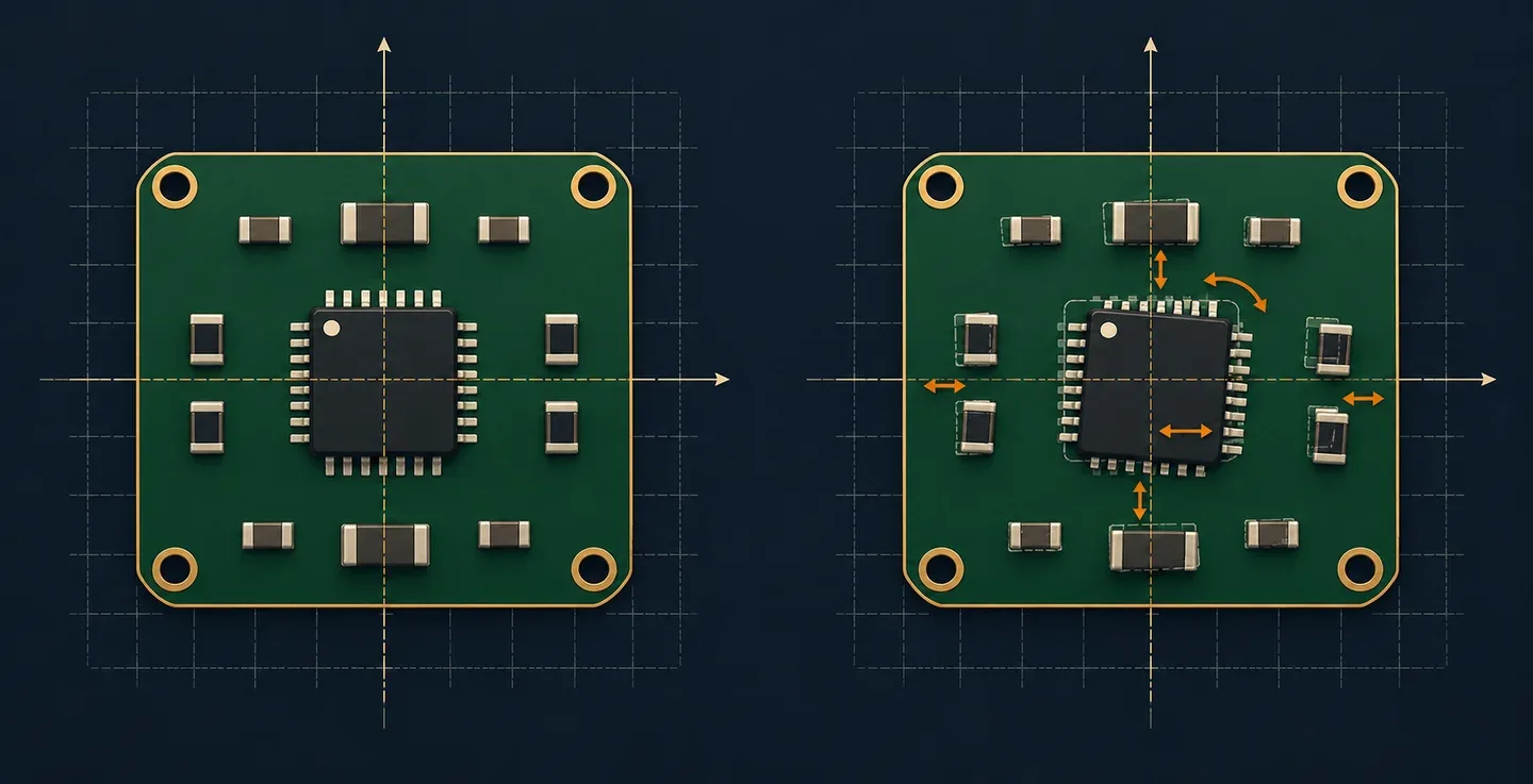
A pick-and-place file tells an assembler where each component belongs and how its footprint is oriented. It is also called a centroid file, component placement list or CPL. A file that imports successfully can still put a polarized part on the wrong pads. Validation must therefore cover the exported coordinates and the physical orientation, not just whether the CSV opens.
This guide focuses on placement data. Use the PCB BOM guide for purchasing fields and approved alternatives, and the assembly file checklist for the complete release package. The illustration and CSV below are invented teaching examples, not customer designs or machine-ready production instructions.
Define the Fields Before Export#
Keep one placement row per fitted reference designator. The minimum useful record identifies the reference, X and Y position, board side and rotation. Add footprint or package information when the supplier requests it. A placement origin is not necessarily the center of the visible package: a library footprint can use an offset anchor. Confirm how such parts are interpreted before changing their exported coordinates.
↔ Swipe horizontally to compare all columns
| Field | Check |
|---|---|
| Reference | Unique and matched to the fitted BOM |
| X / Y | Explicit units and documented origin |
| Side | Unambiguous top/bottom mapping |
| Rotation | Agreed viewing direction and zero-angle convention |
| Package | Matches the footprint and purchased part |
Agree the Origin, Units and Board Revision#
Export placement, fabrication and assembly drawings from the same released PCB revision. Record the origin relative to a recognizable board feature and state whether coordinates describe one board or an entire panel. Do not add panel offsets to a single-board file unless the assembler has asked you to. Otherwise the same offset can be applied twice during programming.
Check the units in the export dialog and the file, rather than inferring them from the number of decimals. A millimeter/inch mismatch produces a 25.4 scale difference. Negative coordinates are not automatically errors; their validity depends on the agreed origin. Check at least two widely separated known locations to distinguish a translation from a scale error, then examine all placements against the board outline.
A Small CSV Example#
The following invented top-side example uses millimeters, a documented board origin and counterclockwise angles viewed from above. Its headers and zero-angle definitions are illustrative, not a universal import format. Map them to your assembler’s requirements. U1 at 90 degrees is meaningful only when both parties know the footprint’s zero-degree orientation.
Designator,MidX_mm,MidY_mm,Side,Rotation_deg
R1,12.500,8.000,Top,0
U1,24.000,16.000,Top,90
D1,31.000,8.000,Top,180
Keep reference designators as text. Check the delimiter, decimal separator and character encoding after any spreadsheet edit. A localized spreadsheet may save decimal commas or change the separator, so reopening the result in a plain-text viewer is useful. Do not hide units or revision notes in undocumented extra rows that an importer might treat as components.
Bottom-Side Mirroring Is a Convention, Not a Guess#
A bottom-side assembly view can look mirrored relative to a top-view coordinate system without the source placement file being wrong. CAD exporters and assembly importers do not all describe the underside in the same way. Confirm the viewing direction, X-axis treatment, angle sign and side labels together. Never apply a blanket X negation or 180-degree rotation simply because the preview looks unfamiliar.
Choose an asymmetric bottom-side component and a recognizable board feature, such as a keyed connector or an offset mounting hole. Compare their relative positions in the CAD assembly drawing and the supplier’s imported preview. Then check the component’s pin 1 against the actual pad numbering. A symmetric resistor can appear correct under a wrong mirror transform and is a poor orientation witness.
Validate Rotation, Polarity and the Fitted Variant#
For ICs, identify pin 1 from the manufacturer’s package drawing and match it to pad 1 in the footprint. For diodes, LEDs and polarized capacitors, use the datasheet’s terminal definition instead of assuming every body stripe or dot means the same thing. Check connector keying as well. A correct numeric angle does not repair an incorrectly numbered footprint.
Reconcile fitted references with the BOM and assembly drawing for the exact variant being ordered. Exclude or clearly identify do-not-populate parts according to the agreed import workflow. Keep fiducials, tooling features and mechanical-only footprints separate from purchased components. Through-hole parts may need placement information or separate manual-assembly instructions; agree that scope rather than silently deleting them from the handoff.
Release Checks and Error Patterns#
A uniform shift suggests an origin mismatch; distances consistently scaled suggest a unit mismatch. Errors limited to the bottom side suggest a view or transform mismatch. A few rotated packages suggest footprint-library orientation differences. These are diagnostic starting points, not proofs: inspect the export settings and the imported placement overlay before editing data. Record any approved correction so the next order does not recreate the same error.
- Confirm revision, variant, units, origin and single-board versus panel scope in the release notes.
- Compare fitted reference sets; resolve duplicates, missing parts and unintended DNP entries.
- Approve top and bottom previews against pad numbering and assembly drawings, including polarized parts.
- Freeze the acknowledged files; route subsequent changes through an explicit revision approval.
Send unresolved orientation questions with the affected reference designators and annotated views when requesting PCB assembly support. Ask for confirmation of the imported placement before authorizing the build. An import preview is a useful release control, but it does not replace assembly inspection or functional testing of the finished board.
Pick-and-Place File FAQs#
Is a CPL the same as a BOM?
No. The BOM identifies what to purchase and fit; the CPL describes placement. Match them by reference designator and variant. Neither replaces the fabrication data or assembly instructions.
Should I manually mirror bottom-side coordinates?
Only when required by the agreed export/import convention. Check an asymmetric part and pad numbering in the supplier preview first. Applying a second mirror to already transformed data can reverse correct placements.
Why does an imported component need an angle correction?
The CAD footprint and assembly library may define zero degrees differently. Verify pin-to-pad mapping with the datasheet, then document the approved correction. Do not apply one correction to every package without checking.
Can I generate the placement file from Gerbers alone?
Use the native PCB layout export whenever possible. Gerbers describe manufacturing geometry and do not reliably provide the complete component identity, variant and orientation intent. Reconstructing placement requires engineering review, not an assumed one-click conversion.
Must every footprint appear in the placement file?
Follow the fitted variant and the assembler’s workflow. DNP parts, fiducials and mechanical features need explicit handling; through-hole parts may use a separate process. Reconcile the expected fitted set rather than assuming the raw footprint count equals the assembly quantity.